Best Practices for Embedded Integration Testing
Planning, dependency analysis, incremental and HIL testing, clear interface contracts, and CI automation to reduce defects in embedded systems.

Embedded integration testing ensures hardware, software, and firmware work seamlessly together in complex systems. This testing phase uncovers issues like timing errors, data mismatches, and unhandled interrupts that unit tests might miss. It’s especially critical for industries like aerospace and automotive, where failures can lead to catastrophic outcomes.
Key takeaways:
- Plan early: Define integration order, dependencies, and test cases before starting.
- Incremental testing: Add components step by step to isolate defects efficiently.
- Use Hardware-in-the-Loop (HIL): Simulate hardware interactions to detect hardware-related issues.
- Automate testing: Integrate tests into CI/CD pipelines for faster feedback and reduced costs.
- Test edge cases: Validate failure scenarios to ensure the system degrades gracefully.
From Unit Test to System Test | Make Sure Your Application Works
Planning and Structuring Integration Tests
Integration testing works best when planned before code integration begins. This means deciding the order in which components will be combined, defining the test cases that will validate their interactions, and outlining strategies to catch defects early. Without a clear plan, debugging can become a tangled mess. Proper planning not only simplifies debugging but also ensures defects are caught when they’re easier - and cheaper - to fix. It also sets the stage for a structured approach to analyzing dependencies.
Analyze Dependencies to Determine Integration Order
Dependency mapping is the key to identifying critical integration paths. Start by examining the system's architecture to understand which modules depend on others and which interfaces pose the greatest risk. For systems heavily reliant on hardware, it’s smart to begin with Hardware Abstraction Layers (HAL), device drivers, and Interrupt Service Routines (ISRs). This bottom-up approach helps uncover timing issues and driver defects early, at a stage where tracing problems is more straightforward.
If the system is more focused on application logic, a top-down approach works better. This method validates high-level control modules first, using stubs to stand in for missing lower-level components. For complex systems, a sandwich strategy - integrating from both the top and bottom simultaneously - can strike a balance. Teams that use formal interface contracts see 60% fewer integration defects and resolve issues 50% faster compared to teams that skip this critical planning step.
Design Test Cases for Key Scenarios
Once the integration order is set, the next step is crafting test cases that target both normal and failure conditions. These tests should cover nominal scenarios as well as edge cases. Pay special attention to interface contracts, which include specifics like data formats, parameter ranges, and return values. For embedded systems, timing requirements are crucial - define maximum allowable latencies, response deadlines, and how the RTOS manages task coordination. For instance, a sensor driver might perform flawlessly on its own, but integration testing could reveal that even a slight delay disrupts the entire control loop.
Error handling tests are equally important. These ensure that failures, like a sensor malfunction, lead to graceful degradation rather than system crashes. Test edge cases, such as ADC conversion limits at 0% and 100%, buffer overflows, and unexpected state transitions. By developing structured test cases for these scenarios, organizations have been able to reduce defect escape rates by up to 74%. Each test should follow a clear structure - setup, exercise, verify, and cleanup - to make tracing failures easier. Thoughtful and precise test case design ensures embedded systems can handle real-world challenges while supporting the broader testing framework discussed earlier.
Incremental Integration Strategies
Incremental integration involves adding components step by step, rather than testing everything at once. This method can cut integration phase defects by 65% compared to the "big-bang" approach, where all components are tested simultaneously. By introducing modules gradually, teams can pinpoint failures more efficiently, without combing through the entire codebase. Additionally, teams adopting this strategy report a 40% reduction in the time required for integration.
The starting point for integration depends on component readiness. If drivers are prepared, begin with low-level modules. If hardware development is behind schedule, start with high-level logic. For complex systems, a sandwich approach - testing from both ends at the same time - allows separate teams to work in parallel, eventually meeting in the middle. Below, we’ll explore bottom-up, top-down, and mixed strategies in more detail.
Bottom-Up and Top-Down Approaches
Bottom-up integration begins with the lowest-level modules, such as Hardware Abstraction Layers (HAL), device drivers, and Interrupt Service Routines (ISRs). These components are grouped into clusters, with test drivers simulating higher-level calls. This approach is particularly effective for identifying timing bugs and hardware-specific issues early. For instance, in automotive sensor processing, integration might start with an ADC driver and sensor calibration HAL (Level 1), then add a digital filter module (Level 2), and finally incorporate business logic for threshold checking (Level 3).
Top-down integration, on the other hand, takes the opposite route. It begins with high-level application logic and control modules, using stubs to represent unavailable lower-level components. For example, in a smart thermostat project, testing might start with the main TemperatureControl_Task while using stubbed sensors and actuators. At the next level, the sensor stub could be replaced with a real data aggregation service, and finally, actual drivers would be added to handle timing and error conditions. This method is ideal for validating system flow and user interfaces early, especially when hardware isn't ready yet.
Hardware-in-the-Loop (HIL) and Mixed Strategies
Hardware-in-the-Loop (HIL) testing integrates firmware with actual hardware while simulating environmental inputs. This approach is essential for catching issues that software-only simulations might miss, such as timing errors, interrupt handling problems, and race conditions. HIL testing can reduce hardware-related defects by 55% during system testing, and in some cases, up to 95% of testing can be completed using HIL simulation before physical hardware becomes available.
"Hardware-in-the-loop (HIL) simulation is the gold standard for developing and validating the most advanced control, protection, and monitoring systems." - OPAL-RT
A 2022 analysis by Array of Engineers highlighted the efficiency of HIL testing. In one case, a system requiring 110 tests saw its execution time drop from 6.6 weeks to just 55 hours using an MHIL system.
Sandwich integration combines both top-down and bottom-up approaches, enabling teams to validate high-level flow and low-level hardware interactions at the same time. This mixed strategy is especially useful for complex systems, as it allows different teams to tackle integration from multiple angles simultaneously.
Define Clear Interface Specifications
When following incremental integration strategies, having clear interface specifications is crucial to avoid miscommunication between components.
Many embedded system bugs only appear during component interaction. A common culprit? Miscommunication at the interface. For example, one module might send measurements in centimeters, while the receiving module expects inches. These mismatches are entirely avoidable with well-defined, straightforward interface contracts. In fact, formal interface specifications can cut integration defects by 60% and speed up issue resolution by 50%. These contracts form a consistent communication framework across hardware, software, and firmware, ensuring smoother collaboration and early validation of key elements.
"Interface design often assumes the status of requirements when the design is baselined... because the thing at the other end of the interface is relying on mutual consistency from the System of Interest." - Robert Halligan, FIE Aust CPEng IntPE(Aus), PPI
Key Elements of Interface Contracts
A solid interface specification should cover several essential aspects:
- Data Definitions: Clearly outline data types, parameter ranges, return values, and serialization formats. For instance, if a sensor module provides temperature readings, specify whether the values are in Fahrenheit or Celsius, the expected range (e.g., -40°F to 257°F), and the data type (e.g., 16-bit signed integer).
- Timing and Synchronization: Document maximum latencies, response times, execution deadlines, and synchronization strategies, especially for multi-threaded or interrupt-driven systems.
- Error Handling: Define failure modes, error codes (e.g., ACK/NAK signals), recovery procedures, and how errors propagate across components.
- Communication Protocols: For hardware-software interfaces, specify protocols like UART, I2C, SPI, or CAN, along with message framing (start/end characters) and integrity checks such as checksums or CRC.
One practical tip: avoid toggle commands like "Power." Instead, use explicit commands like "Power On" and "Power Off" to prevent state desynchronization. Also, include query commands for every configurable value or state, enabling the system to verify its current configuration.
Validate Interfaces Before Development
Before any development begins, establish and review API contracts with all stakeholders involved in the interface. This early validation step - often called a "shift-left" approach - can reduce defect detection costs by 85% compared to fixing issues after deployment.
Design tests to cover both expected scenarios and error cases. For example, if a sensor interface is designed to reject out-of-range values, create test cases that intentionally send invalid data to confirm the error handling works as intended.
Use stubs and mocks to simulate counterpart behaviors, allowing teams to test interface behavior early. This helps identify issues like incorrect state transitions or missing error codes before they escalate into costly problems. Additionally, maintain interface versioning to manage compatibility across different hardware or software updates. Regular stakeholder reviews ensure both sides of the interface are on the same page, reducing the risk of misalignment.
Automate Tests and Use Continuous Integration
Building on the earlier strategies of planning and incremental development, automation and continuous integration (CI) help eliminate the delays caused by manual hardware testing. Automated tests run with every code change, catching bugs as soon as they appear, which speeds up the development process. By 2025, 78% of safety-critical embedded teams are expected to adopt continuous integration practices - up from just 43% in 2020.
"With continuous integration, your software is proven to work (using automated tests) with every new change and when it breaks you fix it immediately".
Adopting CI can significantly boost efficiency, reducing the time spent on the integration phase by up to 40%. This approach lays the groundwork for embedding tests directly into CI/CD pipelines.
Integrate Tests in CI/CD Pipelines
Embedding integration tests into CI/CD pipelines allows for much faster issue resolution. Automated pipelines can deliver feedback in mere minutes, a stark contrast to the days or even weeks needed in manual, hardware-based testing environments. This speed matters: identifying defects during development can reduce the cost of fixing them by 85% compared to finding them after deployment.
A practical approach is to create progressive CI loops, starting with unit tests and gradually scaling up to full system validation. Tools like QEMU and Renode offer simulation options to bypass hardware limitations, enabling parallel testing in the cloud. For physical hardware validation, you can connect devices to your CI pipeline using tools like gitlab-runner installed on a local machine, allowing cloud-based pipelines to execute tests directly on the hardware. To maintain developer productivity, aim for feedback loops that take between 5 and 20 minutes.
Automation Frameworks for Embedded Systems
Once rapid feedback is established, selecting the right automation framework can further streamline the process. For C/C++ unit and integration testing, popular frameworks include GoogleTest, CppUTest, Unity, and TESSY. Commercial tools like Parasoft C/C++test and VectorCAST provide additional features such as code coverage and static analysis. For IoT systems, frameworks like Pytest and Robot Framework are particularly effective at managing integration tests that interact with hardware APIs.
For hardware-in-the-loop (HIL) testing, specialized platforms are essential. Tools like Wind River Simics and Renode allow firmware testing on virtual hardware models, enabling 80% to 95% of software tests to be conducted without physical boards. When it comes to final validation of real-time interactions, industry standards include dSPACE, National Instruments (LabVIEW/TestStand), and Vector CANoe. Additionally, simulation checkpoints can save the system state after booting, letting subsequent tests start from a known good state instantly.
sbb-itb-f3ffd9f
Test Under Realistic Conditions
While earlier sections focused on integration and automation strategies, it's equally important to test systems under real-world conditions to ensure they perform reliably in the field. Automated tests and CI pipelines are great for speeding up development, but they can't fully replicate environmental challenges like temperature fluctuations or power instability. These real-world tests help uncover issues that simulations might miss.
Simulate Environmental Conditions
One effective way to test your embedded device is through Hardware-in-the-Loop (HIL) testing. This method connects your device to a test rig that generates realistic sensor inputs and actuator responses, helping to catch hardware-related defects early. For instance, configurable signal generators can mimic sensor data, while simulators handle actuator responses. In communication-heavy systems, you can replicate real-world bus traffic - like CAN, LIN, or FlexRay - to verify how the system handles varying loads.
Environmental chambers push this further by exposing your system to extreme conditions, such as severe temperatures, high humidity, or intense vibrations. A notable example comes from the COVID-19 pandemic: a global medical device company used HIL simulation and stress testing to address firmware issues in ventilators, ultimately boosting uptime reliability by 45%.
Test Negative Cases and Edge Conditions
Testing isn't just about normal operating conditions - it’s crucial to explore edge cases and negative scenarios to find hidden vulnerabilities. Techniques like boundary value analysis focus on inputs at their limits, where defects are most likely to occur. For example, testing ADCs and PWMs at extreme and median values ensures they function properly across their entire range. Feeding out-of-range or extreme data into the system can validate error handling mechanisms.
"Finding bugs in the negative testing scenarios is where QA can really shine and show big-time value".
Fault injection is another powerful tool. By introducing sensor errors, power instability, or communication bus failures, you can evaluate how well the system handles these disruptions. Using Fault Insertion Units (FIUs) in HIL setups allows you to automate fault simulations, like short circuits or broken wires. During these tests, keep an eye on CPU usage, memory consumption, and timing deadlines to ensure the system stays responsive, even under stress. These rigorous testing practices can reduce defect escape rates by as much as 74%.
Regression Testing and Mocking Strategies
To ensure your software remains reliable as it evolves, regression testing plays a vital role in catching issues early. Coupled with mocking and simulation techniques, these strategies help maintain quality even when hardware or dependencies are unavailable.
Automate Regression Testing
Automating regression tests is key to identifying integration problems quickly. Start by creating a baseline of critical tests, and use tools like Test Impact Analysis (TIA) to focus only on the tests affected by recent changes. This approach significantly reduces execution time, especially in large projects.
For industries governed by strict regulations, bidirectional traceability is essential. By linking requirements directly to test cases and results, you can ensure compliance with safety standards like ISO 26262 or DO-178C. This traceability also simplifies impact analysis when requirements evolve. Statistics show that organizations implementing thorough integration testing detect 70% more defects before reaching the system testing phase, while also cutting integration times by 40%.
Mocks and simulators further enhance regression testing by replicating dependencies, enabling you to test effectively even in the absence of hardware or other components.
Use Mocks and Simulators Effectively
Mocks, stubs, and simulators are indispensable when testing in environments where hardware or complex dependencies are unavailable. Here’s how they work:
- Stubs: Provide basic implementations that return fixed values, often used to satisfy linker requirements.
- Fakes: Offer working but simplified versions of a dependency, such as using a RAM-based buffer to mimic a NOR-flash driver.
- Mocks: Allow you to verify function calls, check argument values, and pre-program specific return sequences. This is particularly helpful for testing failure paths or complex logic.
"Mocks are especially useful when testing failure paths that would likely never happen, or be disastrous if they did happen." - Tyler Hoffman, MCU SDK Engineer
Simulators, like QEMU, replicate hardware behavior, enabling software-in-the-loop testing on a host PC before actual hardware becomes available. This method allows you to achieve comprehensive code coverage by simulating failure scenarios - such as memory allocation issues or sensor malfunctions - that are either too risky or difficult to recreate on real hardware.
As physical hardware components become available, you can gradually replace mocks and stubs with real implementations, increasing the fidelity of your tests. This phased approach ensures you maintain high-quality testing throughout the development lifecycle.
Checklist Summary: Comparing Integration Methods
Embedded Integration Testing Methods Comparison: Bottom-Up vs Top-Down vs HIL vs Sandwich Approaches
Here's a quick-reference checklist summarizing key integration methods, their advantages, and when they work best. Choosing the right approach depends on factors like system complexity, available hardware, and the layers you need to validate early. Each method comes with its own trade-offs in terms of debugging, resources, and suitability for embedded systems.
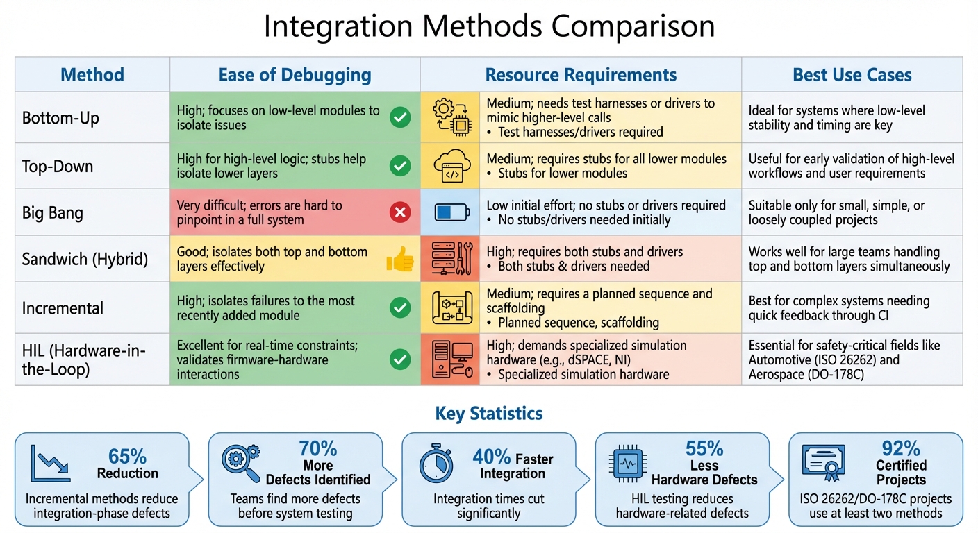
Integration Methods Comparison Table
| Method | Ease of Debugging | Resource Requirements | Best Use Cases |
|---|---|---|---|
| Bottom-Up | High; focuses on low-level modules to isolate issues | Medium; needs test harnesses or drivers to mimic higher-level calls | Ideal for systems where low-level stability and timing are key |
| Top-Down | High for high-level logic; stubs help isolate lower layers | Medium; requires stubs for all lower modules | Useful for early validation of high-level workflows and user requirements |
| Big Bang | Very difficult; errors are hard to pinpoint in a full system | Low initial effort; no stubs or drivers required | Suitable only for small, simple, or loosely coupled projects |
| Sandwich (Hybrid) | Good; isolates both top and bottom layers effectively | High; requires both stubs and drivers | Works well for large teams handling top and bottom layers simultaneously |
| Incremental | High; isolates failures to the most recently added module | Medium; requires a planned sequence and scaffolding | Best for complex systems needing quick feedback through CI |
| HIL (Hardware-in-the-Loop) | Excellent for real-time constraints; validates firmware-hardware interactions | High; demands specialized simulation hardware (e.g., dSPACE, NI) | Essential for safety-critical fields like Automotive (ISO 26262) and Aerospace (DO-178C) |
This table lays out the strengths and challenges of each method, helping teams align their strategy with project requirements and constraints.
Incremental methods, for instance, have been shown to reduce integration-phase defects by 65%. Teams using these approaches identify 70% more defects before system testing and cut integration times by 40%. In safety-critical industries, 92% of projects certified under ISO 26262 or DO-178C rely on at least two integration methods, underscoring the need for rigorous testing in high-stakes environments.
Dependency analysis plays a critical role in defining integration strategies. By pinpointing high-risk interfaces and critical paths, teams can make informed decisions that significantly reduce defects and integration time. For example, teams leveraging HIL testing report 55% fewer hardware-related defects during final system testing. These results highlight how clear interface contracts and strategic testing approaches can streamline the integration process and improve overall system reliability.
Conclusion
Mastering embedded integration testing demands careful planning, thoughtful execution, and ongoing validation. By analyzing dependencies and setting up clear interface contracts early on, teams can slash integration defects by 60% and speed up issue resolution by 50%. These early steps create a solid foundation that supports all subsequent testing efforts.
Incremental integration methods - whether top-down, bottom-up, or a mix of both - help pinpoint defects in newly added components, making debugging more straightforward. Organizations that prioritize thorough integration testing uncover 70% more defects before system testing and cut the integration phase duration by 40%. When paired with Hardware-in-the-Loop testing, teams also reduce hardware-related defects during final testing by 55%. These strategies work hand-in-hand with automated regression testing to improve overall system stability and reliability.
"Catching a bug during integration testing (or earlier) is far cheaper and easier to fix than catching it in full system testing or, worse, in the field." – WizzDev
Automation and continuous integration are becoming indispensable in this landscape. By 2025, 78% of safety-critical embedded teams are expected to adopt continuous integration practices, a leap from just 43% in 2020. This shift highlights the importance of automated regression testing and instant feedback loops in maintaining system performance. Addressing defects during integration instead of after deployment can lower fix costs by up to 85%. Embracing these practices ensures reliable performance for mission-critical embedded systems.
FAQs
What is the purpose of Hardware-in-the-Loop (HIL) testing in embedded systems?
Hardware-in-the-Loop (HIL) testing is a key method for verifying how hardware and software work together in embedded systems. It links the inputs and outputs of the actual controller to a simulated environment, giving developers the tools to test control algorithms, interface timing, and overall system behavior in a controlled setting.
By using HIL testing, potential problems can be identified early, which helps ensure the system is dependable and minimizes development risks - particularly before the physical hardware is fully built or available. This makes HIL testing a crucial process for validating the reliability of advanced embedded systems.
What are the benefits of using incremental integration for testing embedded systems?
Incremental integration is all about adding and testing components one by one. This step-by-step approach makes it simpler to spot and fix defects as they appear. By focusing on integration points, it becomes easier to identify mismatches or interface problems early on, especially those involving hardware and software interactions.
Catching these errors early not only prevents them from affecting the entire system but also makes debugging more straightforward, boosts system reliability, and saves valuable time in the long run.
Why is it important to define clear interface specifications in embedded systems?
Defining clear interface specifications is a cornerstone of successful integration testing in embedded systems. Why? Because it ensures that all system components can communicate without a hitch. Whether it's UART, I²C, SPI buses, or API data formats, well-documented interfaces act like a roadmap for engineers, enabling them to spot mismatches early and sidestep costly errors during deployment.
In embedded systems, where hardware and software are tightly intertwined, even minor discrepancies - like variations in data, timing, or signal levels - can snowball into major problems. Clear specifications make it possible to leverage automated testing to confirm that each module performs as intended, cutting down on bugs and boosting overall reliability. Integrity Tech plays a key role in this process by offering tools and expertise to model, simulate, and validate these complex interactions, helping organizations hit their performance and compliance targets with ease.
Related Blog Posts
Related Blogs
Ready to Transform
Your Customer Management?
Sign up today and see the difference Syncro can make for your business.